Overview
UDP Integration allows to stream data from devices which use a UDP protocol to IoT Hub and converts payloads of these devices into the IoT Hub format.
Please note UDP Integration can be started only as Remote Integration. It could be started on the same machine, where TB instance is running, or you can start in on another machine, that has access over the network to the TB instance.
Please review the integration diagram to learn more.
UDP Integration Configuration
Prerequisites
In this tutorial, we will use:
- IoT Hub instance — iothub.magenta.at;
- UDP Integration, running externally and connected to the cloud IoT Hub instance;
- echo command which intended to display a line of text, and will redirect it’s output to netcat (nc) utility;
- netcat (nc) utility to establish UDP connections, receive data from there and transfer them;
Let’s assume that we have a sensor which is sending current temperature and humidity readings. Our sensor device SN-001 publishes it’s temperature and humidity readings to UDP Integration on 11560 port to the machine where UDP Integration is running.
For demo purposes we assume that our device is smart enough to send data in 3 different payload types:
- Text - in this case payload is SN-001,default,temperature,25.7,humidity,69
- JSON - in this case payload is
1
2
3
4
5
6
7
8
[
  {
    "deviceName": "SN-001",
    "deviceType": "default",
    "temperature": 25.7,
    "humidity": 69
  }
]
- Binary - in this case binary payload is \x53\x4e\x2d\x30\x30\x31\x64\x65\x66\x61\x75\x6c\x74\x32\x35\x2e\x37 (in HEX string).
Here is the description of the bytes in this payload:
- 0-5 bytes - \x53\x4e\x2d\x30\x30\x31 - device name. If we convert it to text - SN-001;
- 6-12 bytes - \x64\x65\x66\x61\x75\x6c\x74 - device type. If we convert it to text - default;
- 13-16 bytes - \x32\x35\x2e\x37 - temperature telemetry. If we convert it to text - 25.7;
- Hex - in this case payload is hexadecimal string 534e2d30303164656661756c7432352e373639.
Here is the description of the bytes in this payload:
- 0-5 bytes - 534e2d303031 - device name. If we convert it to text - SN-001;
- 6-12 byte - 64656661756c74 - device type. If we convert it to text - default;
- 13-16 byte - 32352e37 - temperature telemetry. If we convert it to text: - 25.7;
- 17-18 byte - 3639 - humidity telemetry. If we convert it to text: - 69;
You can select payload type based on your device capabilities and business cases.
Please note that on the machine, where UDP Integration is running, port 11560 must be opened for incoming connections - nc utility must be able to connect to UDP socket. In case you are running it locally, it should be fine without any additional changes.
Uplink Converter
Before setting up an UDP integration, you need to create an Uplink Converter that is a script for parsing and transforming the data received by UDP integration.
To create an Uplink Converter go to Data Converters section and Click Add new data converter —> Create new converter. Name it “UDP Uplink Converter” and select type Uplink. Use debug mode for now.
NOTE Although the Debug mode is very useful for development and troubleshooting, leaving it enabled in production mode may tremendously increase the disk space, used by the database, because all the debugging data is stored there. It is highly recommended to turn the Debug mode off when done debugging.
Choose device payload type to for decoder configuration
|
Now copy & paste the following script to the Decoder function section: The purpose of the decoder function is to parse the incoming data and metadata to a format that IoT Hub can consume. deviceName and deviceType are required, while attributes and telemetry are optional. attributes and telemetry are flat key-value objects. Nested objects are not supported. |
UDP Integration Setup
Go to Integrations section and click Add new integration button. Name it UDP Integration, select type UDP, turn the Debug mode on and from drop-down menus add recently created Uplink converter.
As you mentioned Execute remotely is checked and can not be modified - UDP Integration can be only remote type.
Please note down Integration key and Integration secret - we will use these values later in the configuration on the remote UDP Integration itself.
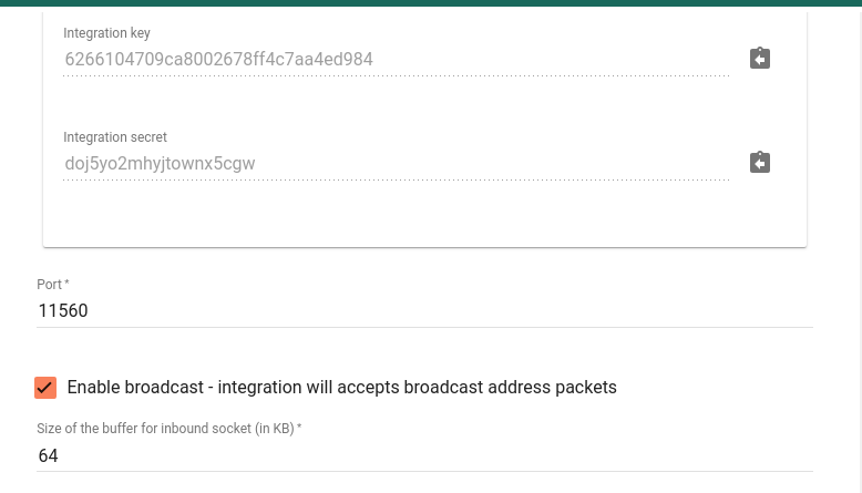
By default UDP Integration will use 11560 port, but you can change this to any available port in your case.
We leave other options by default, but there is brief description of them:
- Enable broadcast - integration will accepts broadcast address packets - a flag indicating that integration will accept UDP packets that were sent to broadcast address;
- Size of the buffer for inbound socket - the size in KBytes of the socket data receive buffer;
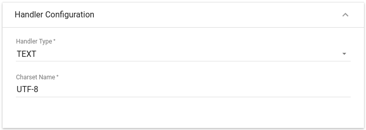
Choose device payload type for Handler Configuration
|
Please select Handler Type as TEXT
To parse payload properly, please make sure that next values are set:
|
|
Please select Handler Type as JSON
|
|
Please select Handler Type as BINARY
|
|
Please select Handler Type as HEX
|
Click Add to save the Integration.
Installing and running external UDP Integration
Please refer to the Remote Integration guide and install UDP Integration service locally or on separate machine.
Please use Integration key and Integration secret from the above section for your UDP Integration configuration.
Send Uplink message
Once IoT Hub UDP Integration has been created, the UDP server starts, and then it waits for data from the devices.
Choose device payload type to send uplink message
|
The command to send a message to the UDP server that is running on localhost (127.0.0.1) will look like this: |
|
The command to send a message to the UDP server that is running on localhost (127.0.0.1) will look like this: |
|
The command to send a message to the UDP server that is running on localhost (127.0.0.1) will look like this: |
|
The command to send a message to the UDP server that is running on localhost (127.0.0.1) will look like this: |
Once you go to Device Groups -> All you should find a SN-001 device provisioned by the Integration. Click on the device, go to Latest Telemetry tab to see “temperature” key and its value (25.7) there.
If your payload contains humidity telemetry, you should see “humidity” key and its value (69) there as well.
Advanced usage: Downlink
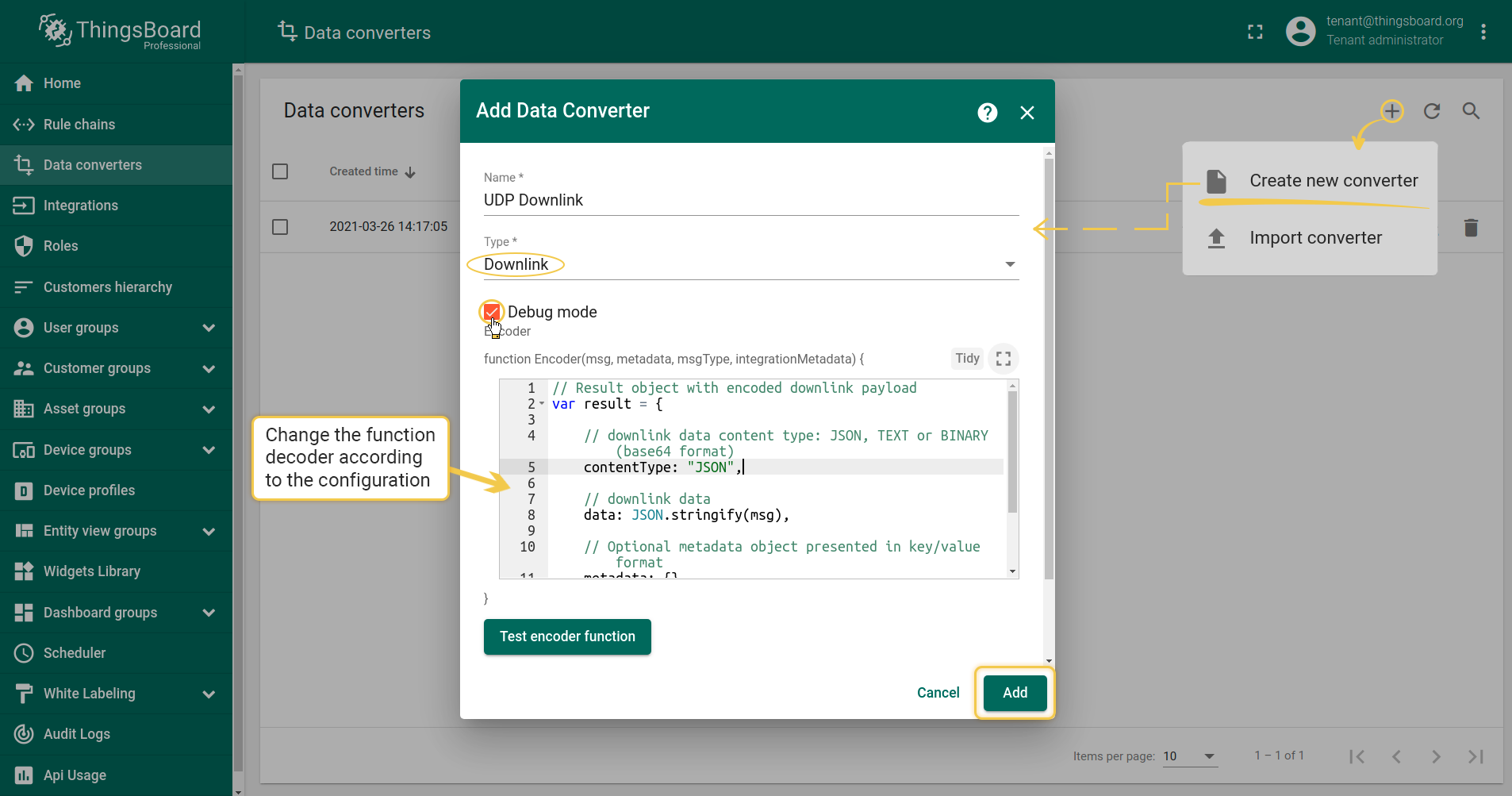
Create Downlink Converter in Data converters. To see events - enable Debug. You can use our example of Downlink Converter, or write your own according to your configuration:
1
2
3
4
5
6
7
8
9
10
11
12
13
14
15
// Result object with encoded downlink payload
var result = {

    // downlink data content type: JSON, TEXT or BINARY (base64 format)
    contentType: "JSON",

    // downlink data
    data: JSON.stringify(msg),

    // Optional metadata object presented in key/value format
    metadata: {}

};

return result;
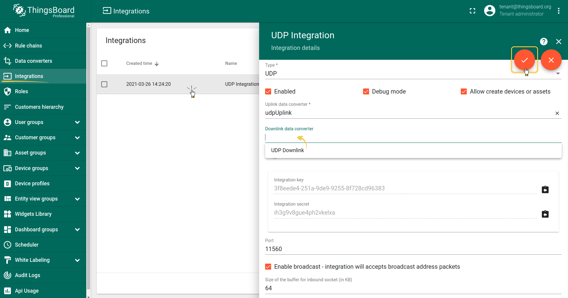
Now you have to add a converter to the integration, optionally configure Cache Size and Cache time to live in minutes (able just for UDP Downlink).
Note: Cache size and Time to live - features, that helps to avoid memory leak when we are storing connections. Cache time to live - time to storage messages Cache size - maximum size of messages for UDP client
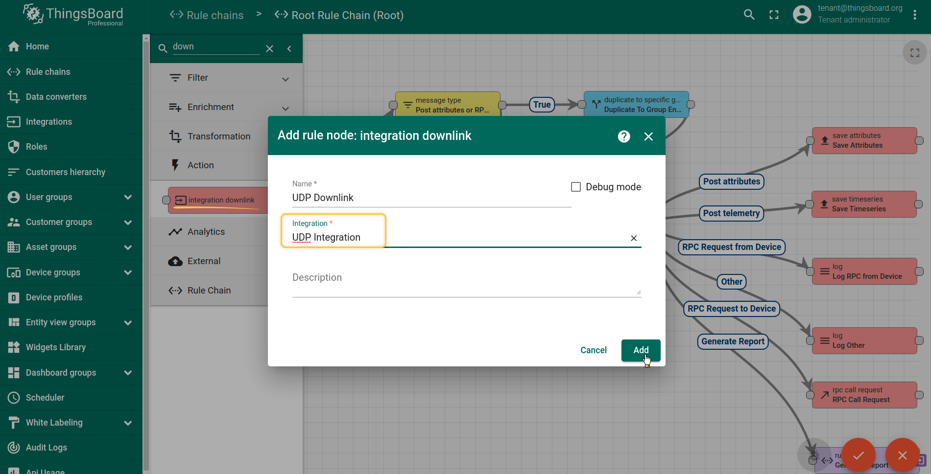
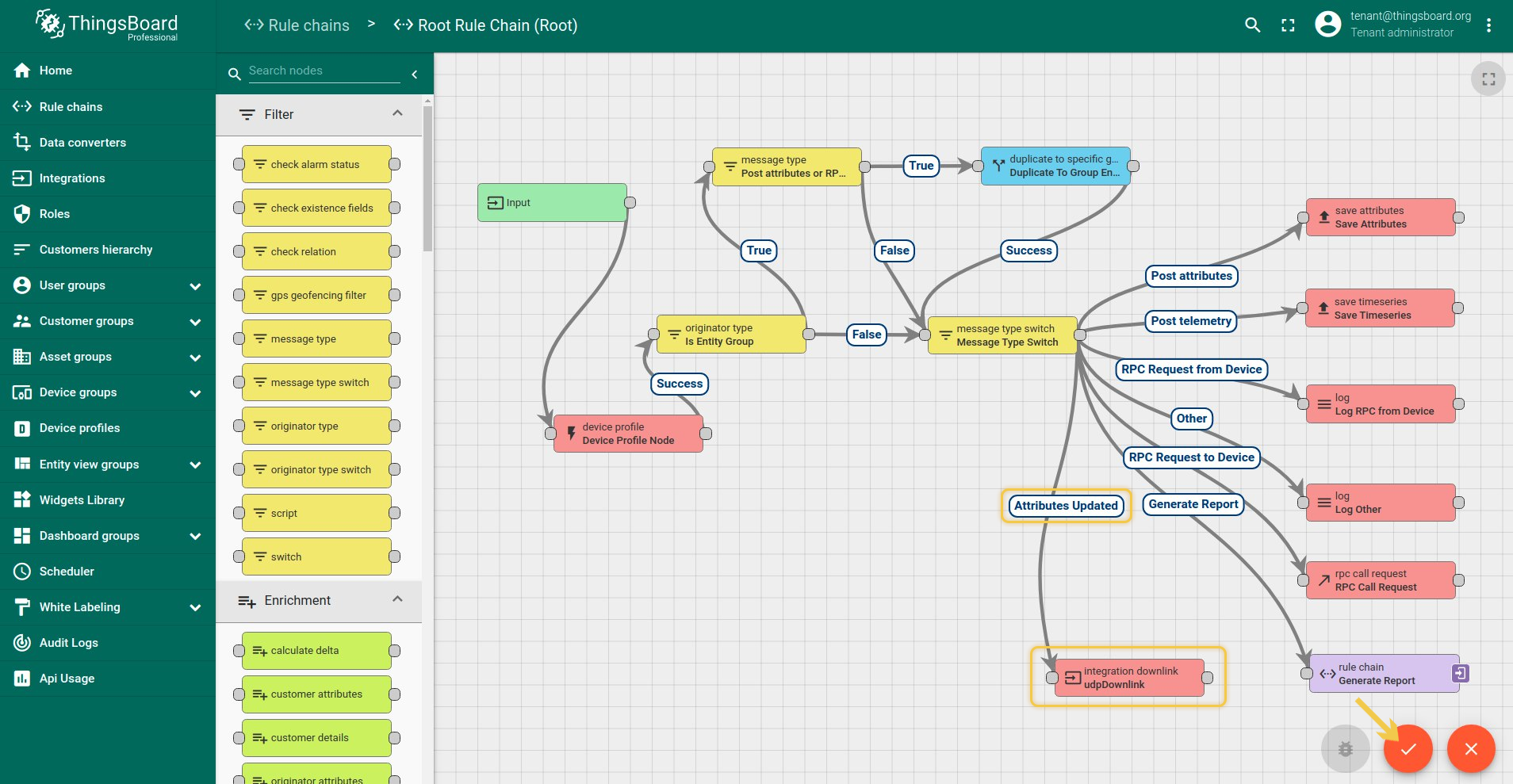
When integration configured and ready to use, we need to go to Rule Chains, choose ‘Root Rule Chain’ and here create rule node Integration Downlink. Input here some name, choose which integration you need to use and tap Add. After this steps, we need to tap on a right grey circle of rule node message type switch and drag this circle to left side of ‘Integration Downlink’, here lets choose Attribute Update, tap ‘Add’ and save Rule node. That’s it!
Test Downlink
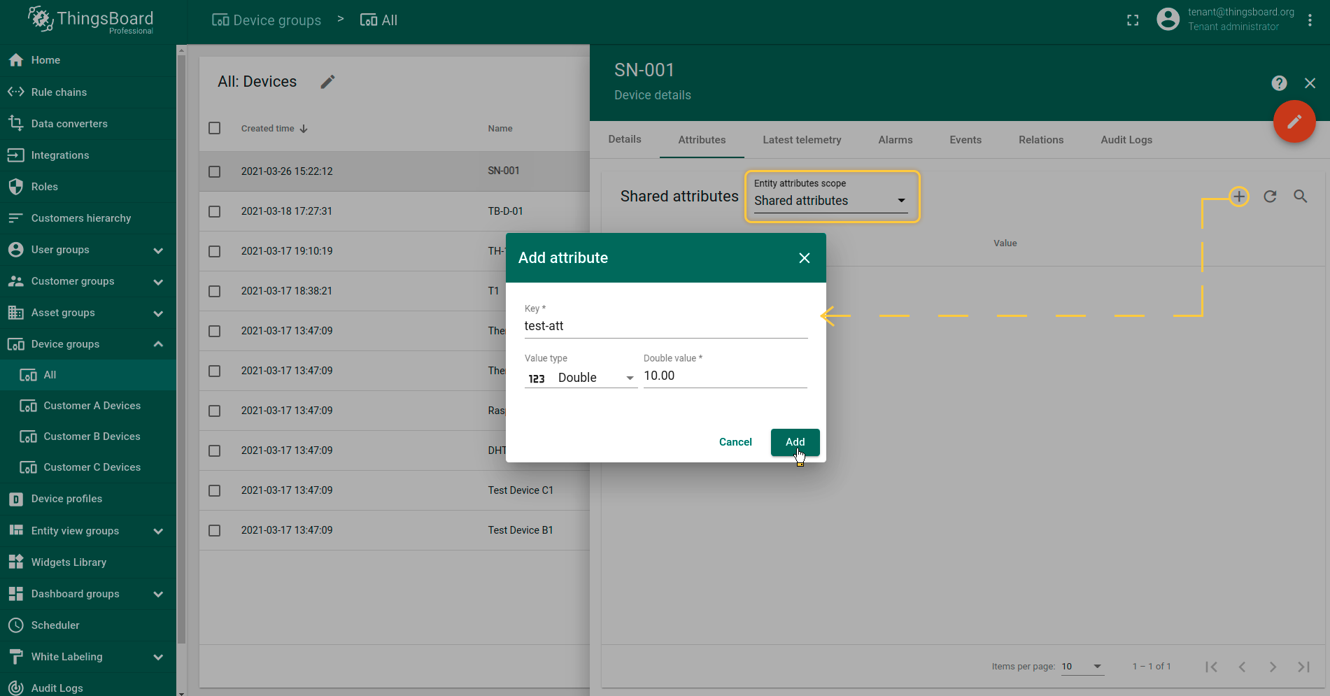
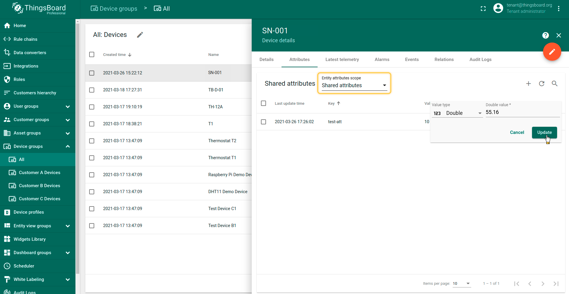
To test downlink you can create some shared attribute on your device, change it, and try to send some Uplink message on this device. And you will see Downlink message.
Also, you can set for Uplink command option -q, for example 120 seconds. This option setting how long you will wait for a response.
If time of connection is over - you will receive this message on next Uplink. See next example:
Note: When you use UDP integration, and your connection established for a long time, you will receive just one Downlink message. All other will be saved on server side and will be sent on next Uplink
Next steps
- Getting started guides - These guides provide quick overview of main IoT Hub features. Designed to be completed in 15-30 minutes.
-
Data visualization - These guides contain instructions how to configure complex IoT Hub dashboards.
-
Data processing & actions - Learn how to use IoT Hub Rule Engine.
-
IoT Data analytics - Learn how to use rule engine to perform basic analytics tasks.
-
Hardware samples - Learn how to connect various hardware platforms to IoT Hub.
-
Advanced features - Learn about advanced IoT Hub features.
-
Contribution and Development - Learn about contribution and development in IoT Hub.

